
Power conversion from rack to chip
Magnetics that enable next-generation switches for AI data centers
Vertical power delivery for 800V DC architectures, unlocking a third more compute per megawatt than conventional designs.
The Problem
AI is scaling faster than power can follow.
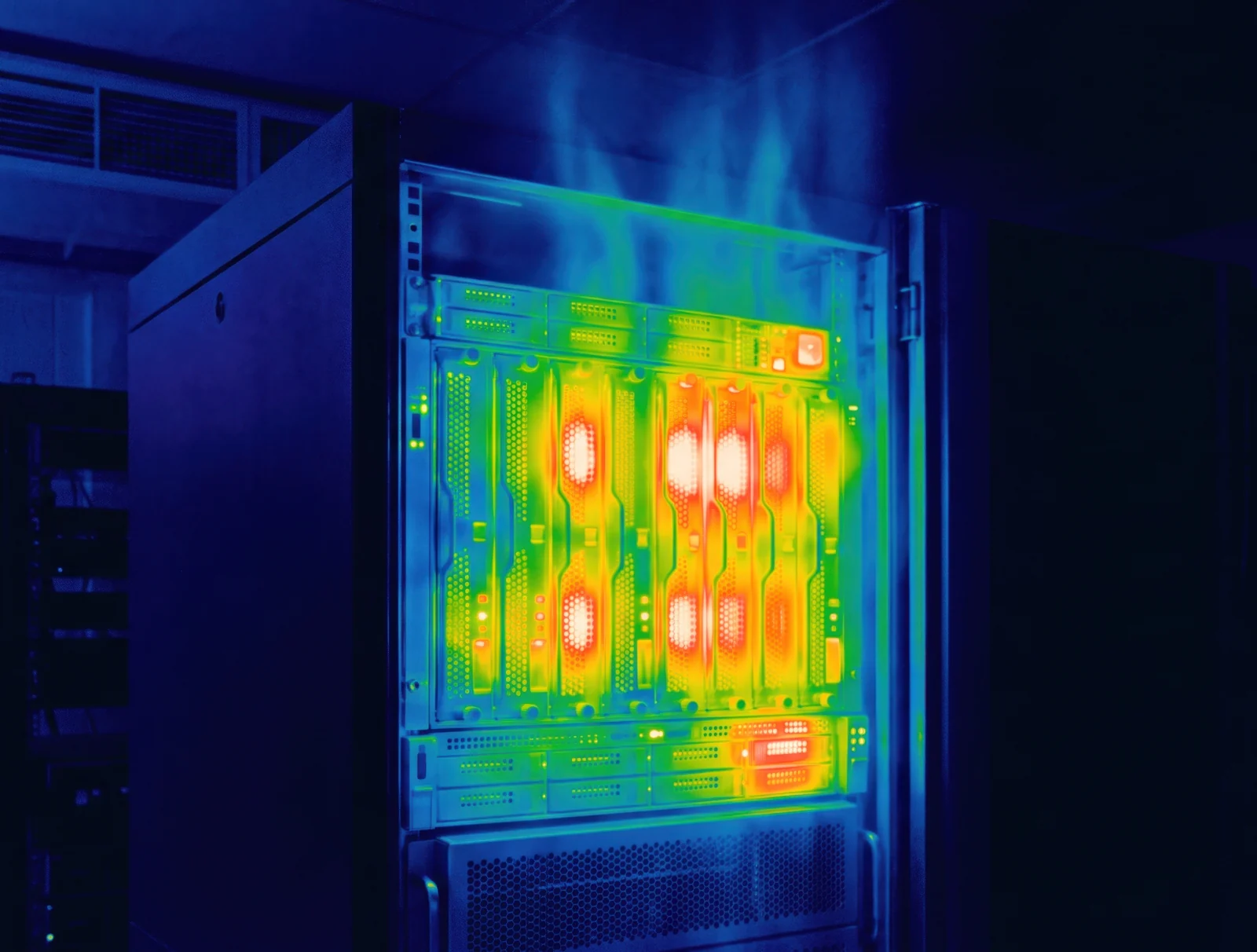
Only 44% of power entering an AI data center reaches the chip. The rest is lost as heat in conversion, cooling, and routing, and the largest loss occurs in the last few centimeters between the regulator and the die.
EnaChip's technology
Our bespoke magnetics unlock IVR and TLVR designs, built for the future of power delivery.
Each starts with a fully electroplated core stack that offers:
Lower Resistance
Thick copper planar windings for high current at low DC resistance, with geometries that cut AC resistance and lower the cooling load
Higher Current
High-flux-density materials for strong current handling in a small core
Smaller Footprint
High volumetric power density in a low-profile, sub-millimeter package
Higher Frequency
Low-loss magnetic materials for efficient switching above 10 MHz
Our magnetics integrate with high-frequency switches, including GaN and advanced silicon, to bring power conversion closer to the load, cutting parasitic losses.
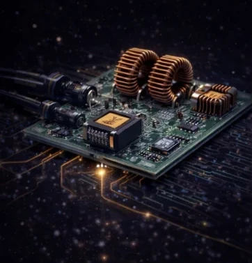
On the Board
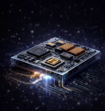
In the Package
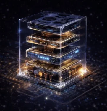
At the Die
The future of data center power delivery
We unleash the performance of next-generation switches at the frontier of power conversion
Sources
Board-to-chip conversion and routing losses from Krishnakumar et al., "A Comprehensive Design Framework for Vertical Power Delivery in High-Performance Computing," arXiv 2606.28837 (June 2026), Fig. 14. Facility cooling from Uptime Institute PUE 1.54 (2026) and CRS R48646 (2025). Site intake and distribution efficiencies from vendor specifications: 80 PLUS Titanium PSU requirements (Texas Instruments SLUP414, 2024); double-conversion UPS efficiency of 96 to 97% (GE TLE Series, Mitsubishi Electric 9900C); 800 VDC solid-state transformer and busbar figures from Wolfspeed (March 2026), SolarEdge (2026), and Alpha & Omega Semiconductor (October 2025) white papers. All figures are units per 100% entering the facility.
Our devices
Our multilayer magnetics suppress core loss at high switching frequencies, which lets our devices shrink to enable low-inductance designs. Electroplating on standard semiconductor equipment cuts manufacturing time dramatically, and our parts drop into any level of your design stack.
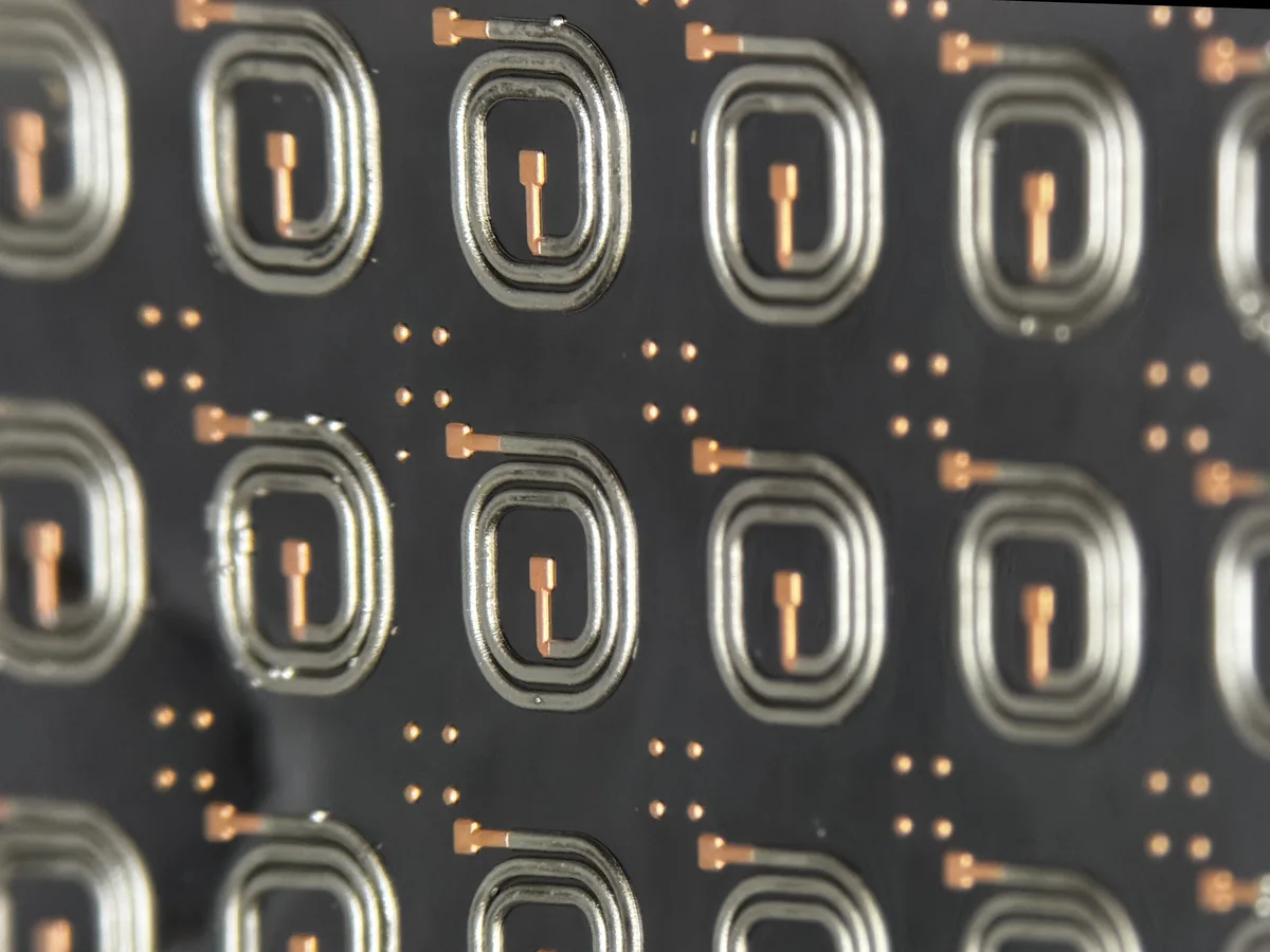
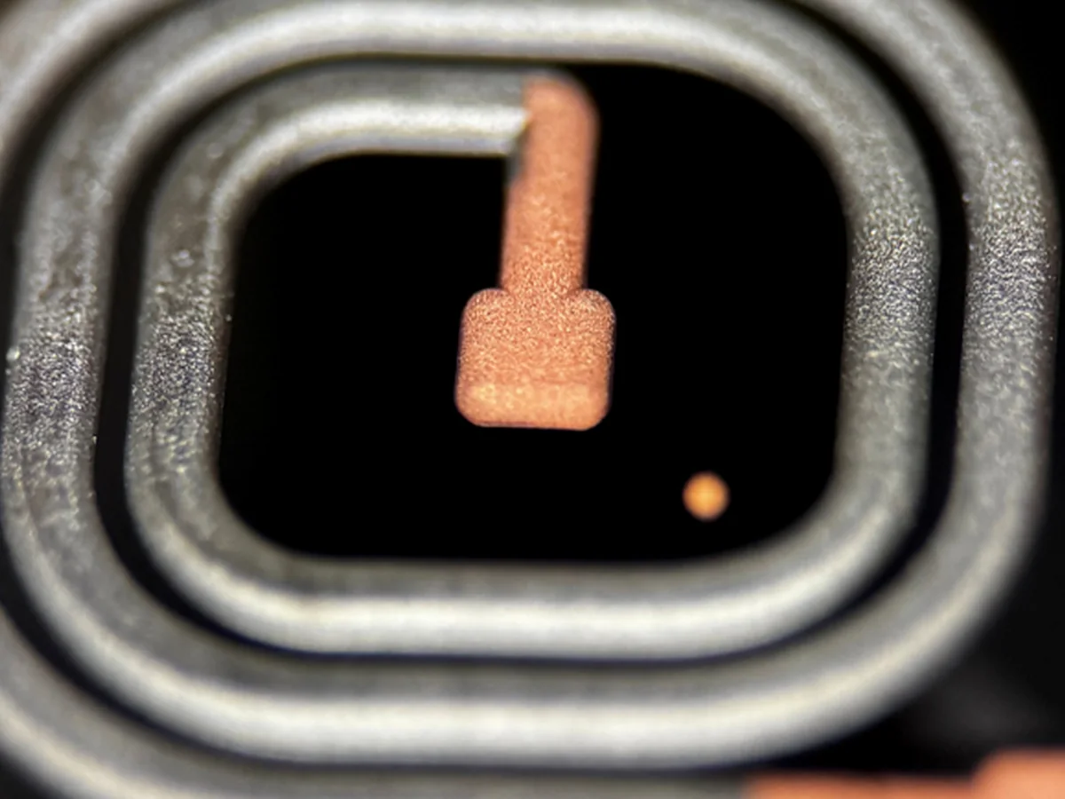
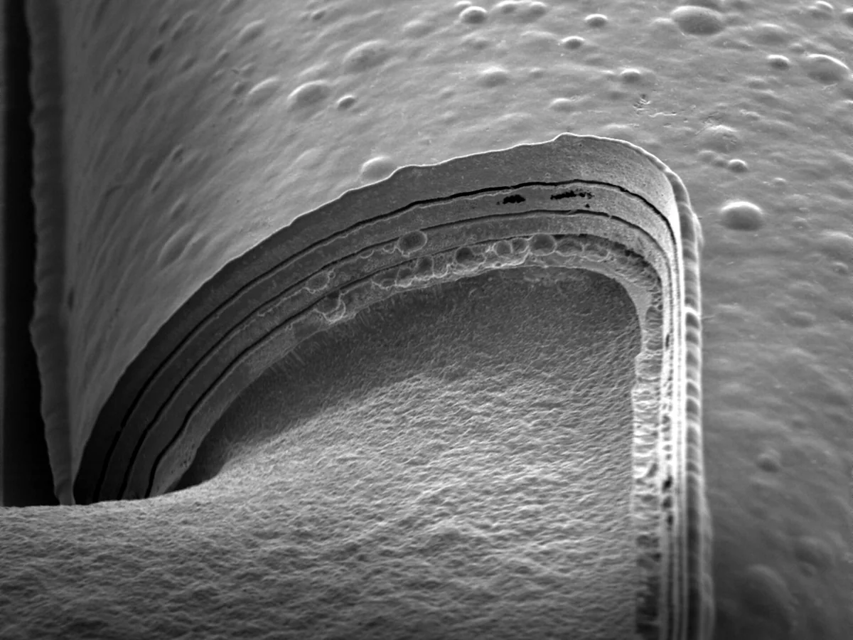
Photographs courtesy of the Singh Center at UPenn (D. Lu)
Shown is our mushroom-core inductor. We build to custom geometries, feature sets, and layer counts.
Our Partners





Connect With Us